Observation is the most basic feature of any science, from astronomy to zoology. One way of making observations is directly, through actual visual contact with the phenomenon either with or without an instrument to aid in the observation. Another way of making observations is indirectly, by using an instrument to actually record instances of the phenomenon. Often the two methods are used together. In this room you will find instruments used in behavior analysis to make both direct and indirect observations.
One dimension of observation is measurement. It is possible to have observation without measurement, but not to have measurement without observation. In a way, measurement is one outcome of observation. This room houses exhibits of instruments used to measure behavior with differing degrees of precision.
DIRECT OBSERVATION & MEASUREMENT
Behavior-Scope (1956)
Like any research, much of the basic research in behavior analysis takes place under highly controlled conditions. With rats and pigeons this means enclosing them in a soundproof, well ventilated operant conditioning chamber (a.k.a. a “Skinner box”) so that distractions from the learning task at hand are minimized. In the case of much basic human operant research, the participant is isolated in a soundproof, well-ventilated room for the same reasons.
 This physical isolation poses a problem. How do we know what the subject is doing in addition to the response we are recording? Even though much of the research in behavior analysis is automated, it is necessary and desirable to observe what the subject/participant is doing. Without these data, one can only infer why certain changes in performance are occurring in the summary data generated by cumulative records and digital counters or, today, computers that control the experiments. Such direct observation, however, has to be made in ways that are minimally intrusive. Otherwise, the observation itself becomes a factor in controlling the behavior, a confounding variable. In the case of rats and pigeons, direct observations can be made unobtrusively through an observation window in the side of the operant chamber or through a small peep hole of the sort commonly found on the front doors of houses and apartments. The latter are especially useful because they provide a “fish eye” look at what is going on inside the enclosed chamber. It is more common today to use tiny cameras than can be located within the experimental space and attached to a computer. These can provide a visual picture of the actual behavior that is occurring. Such cameras also allow construction of permanent records of the behavior. In the 1950s, however, closed circuit TV, if it was available at all, often was prohibitively expensive even for research with human subjects.
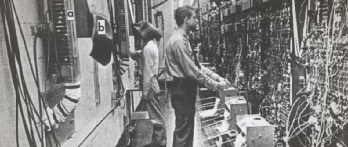
Lindsley (1956) developed one solution for direct observation of human participants – inpatient psychiatric patients – responding on different schedules of reinforcement. That solution is shown in the first photograph in this display. The photo reveals a typical (well, maybe a little more elaborate than “typical”) operant conditioning laboratory of the time, complete with relay racks and cumulative recorders all in a row on the right side. That’s Ogden Lindsley looking over the data as they roll in on the recorders and counters on the relay racks. Now, look behind Lindsley and you see a rather odd thing. There is a fellow with his head covered standing in front of a long tube that extends off the top of the photo. You have to look closely because the tube is partially hidden by a Gerbrands universal feeder, labeled “a”. A better view of the thing into which he is looking is in the foreground on the left side of the photo (labeled “b”). This thing is called a behavior-scope – in essence a sort of periscope designed to view behavior instead of ships - and a version of it was described in detail by Asano and Barrett (1964).
The fellow is observing a psychiatric inpatient, perhaps operating a Lindsley operandum plunger pull device, located in an adjacent experimental room. The patients most likely are receiving reinforcers delivered by the Gerbrands universal feeders as a function of their plunger-pull response.
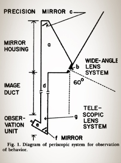
Our observer has his head under a black shroud to prevent light from entering the behavior-scope and reflecting in the mirror in the experimental room. The behavior-scope consists of a long tube with the viewer at one end, in the control room, and the seeking end located above the Lindsley operandum plunger device in the work room. Mirrors and lens inside the tube transmitted the image from the work room to the control room. The diagram of Asano and Barrett’s (1964) version of the behavior-scope appears to the right.
With this simple device, it was possible to observe not only the recorded response, but other, collateral behavior that might be of interest.
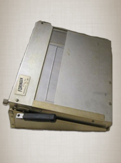
Psion "Workabout" Event Recorder
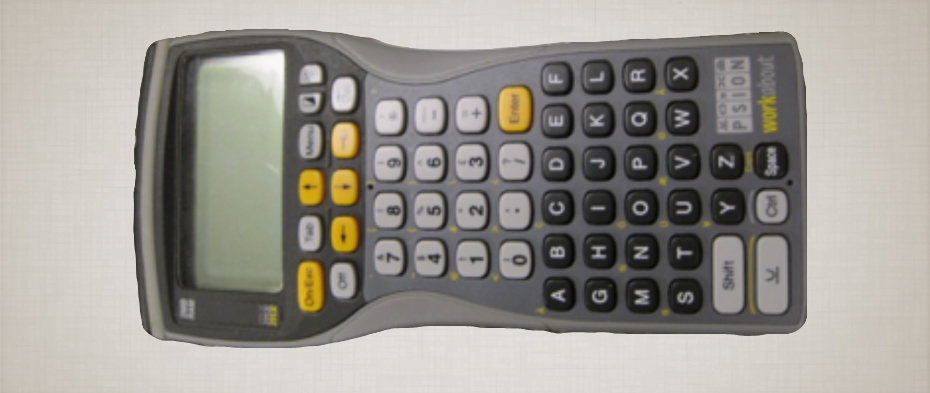 As behavior measurement moved into the digital age, many hand-held devices replaced paper and pencil as the recording medium. The Psion recorder shown here was one such device. Events observed by the observer could be entered by simply pressing preprogrammed buttons. These events then were recorded in real time and could later be downloaded to a “mother” computer for further analysis and storage.
Clipboards for Recording Behavioral Measurements
 The simplest recording system is a pencil and a piece of paper. Before the days of computers, data from digital counters were transcribed onto a data sheet, often affixed to a clipboard like the large one shown here.
The clipboard on the right contains not only space for a data sheet, but also a place for a stop watch, essential when trying to record numbers of behavioral events in a given time period, and a couple of buttons that could be attached to digital counters via the grey cable wrapped around the clipboard. Having the stopwatch located on the clipboard minimizes distraction of the observer by having to look at her wrist or to some other location to see the time count. The button would allow the recording numbers of specific events electronically.
INDIRECT OBSERVATION & MEASUREMENT
Digital Accumulating Counting Devices
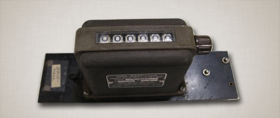
Veeder- Root Digital Counter (1950s)
This was one of the first types of digital counters adapted in the early 1950s for counting responses made when an electrical switch was operated by a rat, pigeon, or human being. The counter operated on 110 volts AC, a common means of programming recording and control apparatus in the early days of operant conditioning. Because of its construction, the counter operated slowly, making it acceptable for recording responses of rats responding on levers or primates and humans responding on a Lindsley operandum
(link to Lindsley operandum). It did not work reliably for pigeons pecking on keys because a pigeon can peck a key for short periods of time as many as 6 times a second!
The photographs of the counter below shows the counter to be just over 3 inches wide and capable of counting up to 999,999 indivudal events. The counter on the right is mounted on a panel so that it could be clipped to power rods on a relay rack. The panel is approximately 7 inches long by 1.5 inches wide. The knobs on the side of the counters allow them to be reset to zero (zeroed out).
Bank of Lehigh Valley Electronics Digital Counters
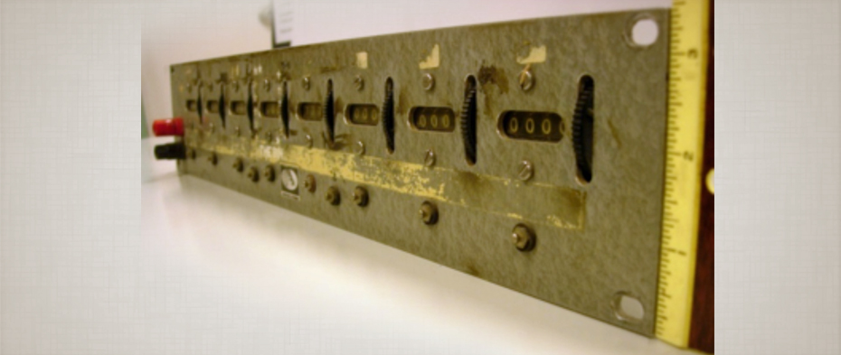 This bank of eight counters mounted horizontally was designed to be attached across the width of a relay rack. The counters were operated by a response transducer that was attached via a snap lead connected to the metal studs shown below each counter. The black plastic wheels to the right of each counter allowed the counter to be reset to zero (zeroed out).
Sodeco 28-volt Digital Counters (1950s & 60s)
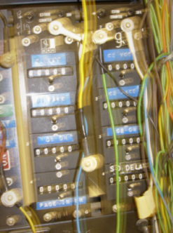
The Swiss firm Sodeco made a compact and reliable digital counter that operated on 28-volt current, which was the preferred power source for electromechanical programming systems (link to controlling environments). It was capable of tracking even a pigeon’s rapid keypecks with considerable accuracy and thus became the “industry standard” from the 1950s until digital counting was replaced by digital computing.
The counter shown here is connected to transducers (electrical response collectors) by the colored wires. The counter is mounted four to a panel and the panels are connected to a relay rack (not shown in the photograph). The small silver lever on the counter allows the counters to be reset to zero (zeroed-out) after the data from them are recorded manually.
These panels of digital counters were manufactured by the Grason Stadler Company.
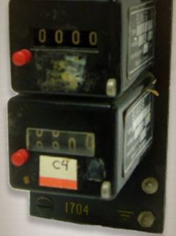
Early Foringer Company Bank of Digital Counters
These counters were a less expensive (and less reliable) substitute for the Sodeco counters. Pushing the red button zeros out the counters. Studs for connecting the counters to the transducer (response translator) are on the bottom of the panel, with only one visible.